where the brackets designate the time average of the quantity inside. Equation 3.37 states that the sum of
the average power possessed by charged particles in V and the total average power passing out through S is always equal to zero. Equation 3.38 shows this relationship in another way:
Consider the case of a planewave incident on an absorbing object, as illustrated in Figure 3.28. Using the impedance relationship for planewaves E/H = 377 (see Section 3.2.8), the magnitude of the Poynting vector for planewave in free space is the familiar expression
P= E2 /377 (Equation 3.39)
When the incident fields impinge on the absorber, E- and H-fields are scattered by the absorber. Poynting's theorem applied to this situation gives
 (Equation 3.40)
Since
 (Equation 3.41)
integrating Ei x Hi, the Poynting vector for the incident
wave, over S would not give the total power transferred from the incident wave to the absorber. Finding this total power from integration of the Poynting vector over S would require knowing the scattered fields and including them in the calculation according to Equation 3.40. Calculating the scattered fields is generally very difficult. It is true that the power transferred to the absorber would be proportional to the Poynting vector of the incident planewave. For a given absorber and a given planewave, for example, the power transferred to the absorber would be twice as much if the incident-power density (Poynting vector of the incident wave) were 2 mW/cm2 as it would if that density were 1 mW/cm2. The actual amount of power transferred to the absorber in each case, however, would depend on the characteristics of the absorber. Thus although the incident-power density of
planewaves is commonly used to indicate their ability to cause power absorption in objects they irradiate, this is
only a relative indication, not an absolute one.
Figure 3.28.
A planewave irradiating an absorber. S is a closed surface used with Poynting's theorem. Scattered fields are produced by the incidence of the planewave on the absorber.
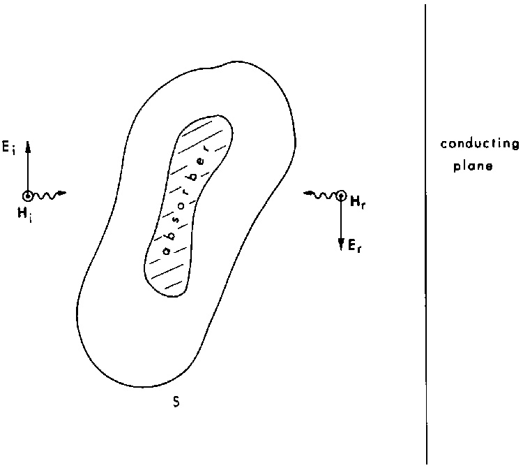
The situation shown in Figure 3.29 further illustrates difficulties sometimes encountered in applying Poynting's theorem. Suppose a planewave is incident on a perfectly conducting plane, thus causing a reflected wave that combines with the incident wave to produce a standing wave (see Sections 3.2.12, 3.3.2) . Then suppose that an absorber is placed in front of the conducting plane at a position where the incident and reflected E-fields add to produce a field of twice the magnitude as that of the incident wave. How would the power transferred to the absorber with the reflector compare to the power transferred to the absorber without the reflector? The first important point is that the Poynting vectors of the incident and reflected wave cannot be added, as indicated by Equation 3.41. So it is not correct to say that the power density incident on the absorber with the reflector would be twice that without it. The principle of superposition can be used with the incident E and H but not with P. The second point is that we cannot draw conclusions from the Poynting vector about power transmitted to the absorber without considering the scattered fields and integrating over a closed surface. For example, suppose that we were to use superposition to add the E-fields and add the H-fields of the incident and reflected waves, and then calculate the Poynting vector from these total fields. Considering what the P would be at a
distance of  /2 from the reflector shows the incorrectness of this procedure. As explained later (Section 3.3.2 and Figure 3.32), the total H at that distance is zero. A calculation of P based on the total E and H at that distance would therefore give a value of zero for P, which does not make sense.
In summary, the Poynting vector should not be used to draw conclusions about energy absorption unless an integration over a closed surface is carried out. Furthermore, the principle of superposition applies to E- and H-fields but not to P.
/2 from the reflector shows the incorrectness of this procedure. As explained later (Section 3.3.2 and Figure 3.32), the total H at that distance is zero. A calculation of P based on the total E and H at that distance would therefore give a value of zero for P, which does not make sense.
In summary, the Poynting vector should not be used to draw conclusions about energy absorption unless an integration over a closed surface is carried out. Furthermore, the principle of superposition applies to E- and H-fields but not to P.
Figure 3.29.
Absorber placed between an incident planewave and a conducting plane.
3.3.2. Interaction of Fields with Objects
Boundary Conditions--At any boundary between different materials, the E and H-fields must satisfy certain conditions. These boundary conditions, which can often be used to help explain qualitatively the interaction of fields with objects, are
 (Equation 3.42)
 (Equation 3.43)
 (Equation 3.44)
 (Equation 3.45)
where subscript n stands for the component of E or H normal (perpendicular) to the boundary, and subscript p stands for the component parallel to the boundary. Subscripts 1 and 2 stand for the two different materials, as indicated in Figure 3.30 for two dielectrics. In each case the field is the total field in the material, which may consist of the fields in both an incident and a reflected wave. These relations hold only at the boundary; with distance away from it, the fields may vary rapidly.
Figure 3.30.
Electric-field components at a boundary between two materials.
The relationships contained in Equations 3.42-3.45 can sometimes be used to understand field behavior qualitatively. For example, if a high-permittivity dielectric object were placed in a low-frequency uniform E-field with the E-field essentially normal to the dielectric object, Equation 3.42 would require that the field inside the object be smaller than the field outside by the ratio of the permittivities of the two materials, the object and its surrounding. This would be true only at the boundary, but it would give a general idea of the field pattern. On the other hand, if the object were placed parallel to the field, Equation 3.43 would require that the field inside the object be equal to the field outside the object at the boundary.
At low frequencies the boundary conditions at the surface of a perfect conductor are that the parallel component of the E-field must be zero. This was explained in Section 3.2.1.
Planar Conductors--When a propagating wave strikes an object, part of the wave is reflected or scattered by the object and part penetrates into the object. The total E- and H-fields at any point outside the object consist of the incident and the scattered fields. The simplest example of scattering is a planewave incident on a planar object. Figure 3.31 shows a planewave normally incident on a planar conductor. When the incident wave enters the conductor, it produces currents that are sources of additional E- and H-fields, called scattered fields (or reflected fields). If the conductor has infinite
conductivity (perfect conductor), the sum of the incident and the scattered fields is zero everywhere inside the conductor. A graph of the total E- and H-fields (sum of the incident and scattered fields) to the left of the perfect conductor is shown in Figure 3.32: (a) shows the total E-field as a function of position for times t1 and t2. At any instant of time, the variation of the field with position is sinusoidal; and at any position, the variation of the field with time is sinusoidal. As the field varies
through a full cycle in time, the envelope of the field varies with position (Figures 3.32(b) and (c)). These wave
patterns are identical to those for voltage and current on a two-conductor transmission line with a short at the end
(Figure 3.23), and the same definitions are made for nodes, standing wave, etc. The nodes for the E-field occur at multiples of half a wavelength from the conductor, and the E-field is zero at the surface of the conductor. The H-field is not zero at the surface of the conductor, but the nodes for H are still spaced a half wavelength apart. Remember that E and H are constant everywhere in a plane perpendicular to the direction of propagation. The patterns shown in Figure 3.32 thus represent the magnitudes of E and H in planes parallel to the conductor. At the nodes, the E and H are zero everywhere in that plane.
Figure 3.31.
Planewave incident on a planar conductor. The conductor produces a scattered wave.
Figure 3.32.
Total fields, incident plus scattered.
(a) Total E-field as a function of position at two times, t1 and t2.
(b) Total E-field as a function of position at various times through a full cycle, and the envelope of the
standing wave.
(c) Total H-field as a function of position at various times through a full cycle, and the envelope of the
standing wave.
Figure 3.33 is a diagram of a planewave obliquely incident on a perfect planar conductor. In this case the
angle of reflection is equal to the angle of incidence. The angles are defined as the angles between the direction of
propagation and the normal to the planar conductor. The sum of the incident and scattered waves for oblique incidence is also a standing wave, but in this case the nodes do not occur at half-wavelength spacing. Their spacing depends on the angle of incidence. For large angles of incidence, the spacing between nodes is much smaller than half a wavelength.
Figure 3.33.
Planewave obliquely incident on a planar conductor.
Planar Dielectrics--When a planewave is incident on a planar dielectric, the incident wave produces currents in the dielectric which produce additional fields, just as a conductor does. Unlike the fields inside a conductor, however, the fields inside a dielectric do not necessarily add to zero. A planewave incident on a planar dielectric produces scattered fields outside the dielectric and a wave inside the dielectric called the transmitted (refracted) wave, as shown diagrammatically in Figure 3.34 for oblique incidence. With a lossy dielectric (see Section 3.2.6), the transmitted wave is attenuated as it travels into the dielectric, becoming essentially zero at some depth related to the  " of the dielectric. For large ", the transmitted wave does not penetrate very far into the dielectric.
Figure 3.34.
Planewave obliquely incident on a planar dielectric.
Nonplanar Objects--The scattering of E- and H- fields by nonplanar objects is more complicated than that by planar objects. The scattering depends on the size, shape, and material properties of the object and the frequency of the incident fields. If the object is very small compared to a wavelength of the incident fields or if the object's relative permittivity is very close to unity, not much scattering occurs. When the object's size is comparable to or larger than a wavelength, significant scattering generally occurs. More specific information about scattering and absorption by biological tissue is given next.
The permeability of biological tissue is essentially equal to that of free space; in other words, biological tissue is essentially nonmagnetic. The permittivity of biological tissue is a strong function of frequency. Figure 3.35 shows the average ' and " for the human body as a function of frequency. Calculations have shown that the average ' and " for the whole human body are equal to approximately two-thirds that of muscle tissue. At frequencies below about 1 MHz, body tissue is anisotropic; i.e., conductivity in one direction is significantly different from the conductivity in another direction.
Permittivity generally decreases with frequency. This manifests the inability of the charges in the tissue to respond to the higher frequencies of the applied fields, thus resulting in lower permittivity values.
In tissue the " represents mostly ionic conductivity and absorption due to relaxational processes, including friction associated with the alignment of electric dipoles and with vibrational and rotational motion in molecules.
The absorption of energy by an object irradiated by electromagnetic fields is a strong function of frequency. Many calculations of absorbed energy, although generally very difficult, have been made; and significant data, both calculated and measured, are available. Absorption characteristics are explained below, first for planar models, which are the simplest but least representative of humans, and then for more realistic models.
Planar Models--Although planar models do not represent humans well, analyses of these models have provided important qualitative understanding of energy-absorption characteristics. When a planewave is incident on a planar dielectric object, the wave transmitted into the dielectric attenuates as it travels and transfers energy to the dielectric (as explained in Section 3.3.2). For very lossy dielectrics, the wave attenuates rapidly. This characteristic is described by skin depth--the depth at which the E- and H- fields have decayed to e-1 (e-1 = 0.368) of their value at the surface of the dielectric. Skin depth is also the depth at which the Poynting vector has decayed to e-2 (e-2 = 0.135) of its value at the surface. For a planewave incident on a planar dielectric, skin depth is given by
 m (Equation 3.46)
where f is the frequency in MHz. Figure 3.36 shows skin depth as a function of frequency for a planar
dielectric with a permittivity equal to two-thirds that of muscle tissue (see Figure 3.35).
Figure 3.35.
Average permittivity of the human body (equivalent to two-thirds that of muscle tissue) as a
function of frequency.
At higher frequencies, the skin depth is very small; thus most of the energy from the fields is absorbed near the surface. For example, at 2450 MHz the skin depth is about 2 cm; at 10 GHz, about 0.4 cm.
Figure 3.36.
Skin depth versus frequency for a dielectric half-space with permittivity equal to two-thirds that of muscle.
The results for planar models have a characteristic generally true for other objects as well: At low frequencies the fields penetrate much deeper than at high frequencies. At very high frequencies any lossy-material heating due to planewave irradiation will be primarily surface heating.
Other Models--Other models--spheres, cylinders, prolate spheroids, block models (cubical mathematical cells arranged in a shape like a human body)-have been used to represent the human body in calculating and measuring energy absorbed during planewave irradiation. The internal E and H are a function of the incident fields, the frequency, and the permittivity and size and shape of the object. Some typical absorption results and characteristics are given in the following sections. Especially important for nonplanar objects are the effects of polarization of the incident fields.
Orientation of incident E- and H-fields with respect to the irradiated object has a very strong effect on the strength of fields inside the object. This orientation is defined in terms of polarization of the incident fields.
Polarization for objects of revolution (circular symmetry about the long axis) is defined by the incident-field vector--E, H, or k -- parallel to the long axis of the body. The polarization is called E polarization if E is parallel to the long axis, H if H is parallel, and K if k is parallel. This definition is illustrated in terms of prolate spheroids in Figure 3.37.
Figure 3.37.
Polarization of the incident field with respect to an irradiated object.
For objects (like the human body) that are not objects of revolution, six polarizations are defined, as illustrated in Figure 3.38 for ellipsoids . The ellipsoid has three semiaxes with lengths a, b, and c, where a > b > c. The polarization is defined by which vector (E, H, or k) is parallel to which axis. For example, EHK polarization is the orientation where E lies along a, H lies along b, and k lies along c.
Figure 3.38.
Polarization for objects that do not have circular symmetry about the long axis.
Definition--In dosimetry, the transfer of energy from electric and magnetic fields to charged particles in an absorber is described in terms of the specific absorption rate (SAR). "Specific" refers to the normalization to mass; "absorption," the absorption of energy; and "rate," the time rate of change of the energy absorption. SAR is defined, at a point in the absorber, as the time rate of change of energy transferred to charged particles in an infinitesimal volume at that point, divided by the mass of the infinitesimal volume. From Equation 3.35
 (Equation 3.47)
where  m is the mass density of the object at that point. For sinusoidal fields, the time-average SAR at a point is given by the term <Pc> / m in Equation 3.38. This is also called the local SAR or SAR distribution to distinguish it from the whole-body average SAR. The average SAR is defined as the time rate of change of the total energy transferred to the absorber, divided by the total mass of the body. From Poynting's theorem for the time-average sinusoidal steady-state case (see Equation 3.38), the whole body average SAR is given by
 (Equation 3.48)
where M is the total mass of the absorber. In practice, the term "whole-body average SAR" is often shortened to just "average SAR."
The local SAR is related to the internal E-field through Equation 3.17:
 (Equation 3.49)
Thus if the E-field and the conductivity are known at a point inside the object, the SAR at that point
can easily be found; conversely, if the SAR and conductivity at a point in the object are known, the E-field at that point can easily be found. Traditionally P has been called absorbed-power density, and the relation in Equation 3.49 illustrates why SAR is also called absorbed power density. The bioelectromagnetics
community, however, has generally accepted SAR as the preferred term.
SAR Versus Frequency--SAR is an important quantity in dosimetry both because it gives a measure of the energy absorption that can be manifest as heat and because it gives a measure of the internal fields which could affect the biological system in ways other than through ordinary heat. The internal fields, and hence the SAR, are a strong function of the incident fields, the frequency, and the properties of the absorber. Since any biological effects would be caused by internal fields, not incident fields, being able to determine internal fields or SARs in people and experimental animals for given radiation conditions is important. Without such determination in both the animal and the person, we could not meaningfully extrapolate observed biological effects in irradiated animals to similar effects that might occur in irradiated people.
The general dependence of average SAR on frequency is illustrated by Figures 3.39 and 3.40 for models of an
average-sized man and a medium-sized rat for the three standard polarizations. For E polarization a resonance occurs
at about 80 MHz for the man; at about 600 MHz for the rat. From these two graphs the resonance frequency appears to be related to the length of the body, and indeed it is. In general, resonance occurs for long thin metallic objects at a frequency for which the object is approximately one-half of a free-space wavelength long. For biological bodies, resonance occurs at a frequency for which the length of the body is about equal to four-tenths of a wavelength. A more accurate formula for the resonant frequency is given in Section 3.5. Below resonance the SAR varies approximately as f2 ; and just beyond resonance, as 1/f.
Figure 3.39.
Calculated whole-body average SAR frequency for model of an average man for three standard polarizations. The incident-power density is 1 mW/cm2.
Figure 3.40.
Calculated whole-body average SAR versus frequency for model of a medium-sized rat for three standard polarizations. The incident-power density is 1 mW/cm2
Figures 3.39 and 3.40 also indicate that below resonance the SAR is generally higher for E polarization, intermediate for K, and lower for H. Again, this is generally true. These characteristics can be explained by two qualitative principles:
- The SAR is higher when the incident E-field is more parallel to the body than perpendicular.
- The SAR is higher when the cross section of the body perpendicular to the incident H-field is larger than when it is smaller.
The average SAR is higher for E polarization because the incident E-field is more parallel to the body than perpendicular to it, and the cross section of the body perpendicular to the incident H-field is relatively
larger (see Figure 3.37). For H polarization, however, the incident E-field is more perpendicular to the body
than parallel to it, and the cross section of the body perpendicular to the incident H-field is relatively
smaller; both conditions contribute to a lower average SAR. The average SAR for K polarization is intermediate between the other two because the incident E-field is more perpendicular to the body, contributing to a lower SAR; but the cross section perpendicular to the incident H-field is large, contributing to a larger SAR.
When a man is standing on a perfectly conducting ground plane, for E polarization the ground plane has the effect of making the man appear electrically to be about twice as tall, which lowers the resonant frequency to, approximately half of that in free space. For a man on a ground plane, the graph of SAR versus frequency for E polarization would therefore be almost like the one in Figure 3.39 but shifted to the left by approximately 40 MHz. This is generally true for objects on ground planes for E polarization.
Another important qualitative characteristic is that when the incident E-field is mostly parallel to the body, the average SAR goes up if the body is made longer and thinner. Some of these "rules of thumb" are summarized in Section 3.5, More detailed information about SAR characteristics is given in Section 5.1.

Go to Chapter 3.4
Return to Table of Contents.
Last modified: June 24, 1997
© October 1986, USAF School of Aerospace Medicine, Aerospace Medical Division (AFSC), Brooks Air Force Base, TX 78235-5301